C and C++ Finite State Machine Framework
Author: Thomas Block
$Date: 2017-01-09 20:36:39 +0100 (Mo, 09 Jan 2017) $
This is an event driven Finite State Machine (FSM) framework in C++ and C including a PERL script
for generating c++ code from a transition table.
Goals
The goals are:- Easy to use
- A separation of the state actions from the transitions.
- Definition of the transitions and states in an easy to handle table.
- Configurable entry and exit behaviour.
- Possible use of a superstate.
- Creation of an UML diagram from the table with PlantUML.
- Creation of the C++/C code template from the transition table.
- Option to use macros or to expand everything in plain code.
- Few overhead
New since last release
The generated C++ file (options -sm and -sw) contains now doxygen conform comments.Provided files:
- For C++
- For C
- A PERL script with following powerfull features:
- Converting the transition table in a PlantUML file so you can have a graphical documentation of the states and transitions.
As an example see Figure 2 generated from the fsm.cpp file. - Creating an FSM C++ template from the transition table using the base class in fsm.hpp or without the base class.
- Creating an FSM C template from the transition table using functions of module fsm.h or without the module.
- Converting the transition table in a PlantUML file so you can have a graphical documentation of the states and transitions.
Questions
You can send an EMAIL to Tom. I cannot promise to answer, but will check my emails and may implement suggestions, if I have time.Concept
In UML a simple state is defined as a box with a name and some more description e.g. the boxes with the names State1 and State 2 in Figure 1.To get a state machine the boxes are connected with arrows telling when the state machine has a transition from one state to the other or to itself (see Figure 1 from State1 to State2).
The transition to State 2 in the state machine of Figure 1 happens when
EVENT occurs and when the condition defined by [guard]
is true. Before entering the new state the action defined by /action
is executed.In our framework the action is optional and [guard] also when it is set to true.

Figure 1: simple UML state machine
As an example of the C++ FSM framework the States and the transitions are defined in the transition table as follows:
// state type, event type
FSM_TT(tState, tEvent)    // start of transition table
  //   current state, next state, event, guard action
  FSM_TT_BEG( State1, State2, EVENT, guard1, action() )
  FSM_TT_CNT(         State1, EVENT, guard2, action() )
FSM_TT_END                // end of transition table

// <FSM_ST><entry> State1
action1.1();
// <FSM_ST>

// <FSM_ST><do> State1
if( EVENT1.1 == getEvent() ) {
  consumeEvt();
  action1.3();
}
// </FSM_ST>

// <FSM_ST><exit> State1
action1.2();
// </FSM_ST>

// <FSM_ST><entry> State2
action2.1();
// </FSM_ST>

// <FSM_ST><do> State2
if( EVENT2.1 == getEvent() ) {
  consumeEvt();
  action2.3();
}
// </FSM_ST>

// <FSM_ST><exit> State2
action2.2();
// </FSM_ST>
Table 1: Transition Table
withtState and tEvent just being enums defined as:
// available states
typedef enum { eStateVoid=0, State1, State2 } tState;
// available events
typedef enum { eEventVoid=0, EVENT, EVENT1.1, EVENT2.1 } tEvent;
The initialization and exit of the FSM is done in the part controlling the FSM (see the main function below).
As seen above a state is represented in the transition table as an enum value.
The actions executed by the state machine are defined as methods.
In C++ the methods of the class (here FsmMy) implementing the state machine will have methods as follows:
void FsmMy::doState1 (void)
{
  TRACE_STATE_ENTRY;
  if( isEntry() ) {
    // do entry action1.1
  }
  if( EVENT1.1 == getEvent() ) {
    // if we consume an event in a state,
    //   we have to tell that to the base class
    consumeEvt();
    // do normal action1.3
  }
  if( isExit() ) {
    // do exit action1.2
  }
}

void FsmMy::doState2 (void)
{
  TRACE_STATE_ENTRY;
  if( isEntry() ) {
    // do entry action2.1
  }
  if( EVENT2.1 == getEvent() ) {
    // if we consume an event in a state,
    //   we have to tell that to the base class
    consumeEvt();
    // do normal action2.3
  }
  if( isExit() ) {
    // do exit action2.2
  }
As you can see the entry and exit parts are just if clauses.
Note: In this framework it is a must to use the
isEntry and isExit methods, even if there are no actions to do.
The reason is that internal variables are set and the state scheduler is called. The last part is to connect the enum for the State with the method. This is done as follows:
FSM_ST_TO_MTHD_BEG(tState)
  FSM_ST_TO_MTHD( State1, doState1() )
  FSM_ST_TO_MTHD( State2, doState2() )
FSM_ST_TO_MTHD_END
That is quite easy, isn't it?
For a test you need a main function which gets the events and dispatches it. So something like:
int main (void)
{
  FsmMy fsm;
  // default event
  tEvent evnt = eEvntVoid;
  // initialize the state machine with state 1
  // so process will start with state1 execution.
  // when getEvent returns eEvntVoid the program is stopped
  fsm.init( State1 );
  do   {
    evnt = getEvent();
    fsm.dispatch( evnt );
  } while( evnt != eEvntVoid );
  return 0;
}
C++/C Framework
The framework consists of only one h file (one for C and one for C++). So you just need to include it in your state machine implementation and derive from the base class Fsm or use the functions provided. This distribution is available under the 3-clause-license, providing a wide flexibility in usage.Compiling / Generating diagrams:
Preconditions:- Perl interpreter for running Perl scripts, e.g. Strawberry Perl , which also contains the GCC tool chain.
- E.g. GCC toolchain for compiling a runnable executable from the example files
- PlantUML tool for generating the diagrams (this also requires a specific version of Graphviz software).
Creating a state chart
Okay so far that is not really much new. But with the perl script we get a bit spice on it.First you can create very easy a state chart. When you have installed all the necessary stuff, just type:
perl fsm2plantuml_pl -tt transition_table_file > state_chart.uml.This creates the file state_chart.uml which is converted to a state chart uml graphic automatically, e.g. by the tool PlantUML File Watcher.
Creating the state machine C++/C file from the transition table
Not hot enough? Okay some more spice.How would it be just having a transition table and generating the code framework from this? That would save some time of coding and prevent some errors. Therefore e.g. save Table 1 in file transition_table_file.
Call the perl script just with an additional option:
| C++ | C |
|---|---|
perl fsm2plantuml_pl -tt transition_table_file -cpp MyFsm -base > MyFsm.cpp |
perl fsm2plantuml_pl -tt transition_table_file -c MyFsm -base > MyFsm.c |
You just need to add the parts which make the specific behaviour of your state machine (the bold parts in doState1 and doState2 from above).
Also you need to have a look at the TODO parts.
When filled correctly compile and execute on a e.g. Windows command shell with.
| C++ | C |
|---|---|
cls && g++ MyFsm.cpp -o fsm.exe && fsm |
cls && gcc MyFsm.c -o fsm.exe && fsm |
Note: The parameter for FSM_TT(... macro vary between the C and C++ framework (please have a look in the specific files). The script takes care about that and creates the correct FSM_TT macro included in the C template.
More Code generator (script) options / Examples
The PERL script is much more powerful.It can create the template for use of the base class.
If you do not like a base class with virtual functions at all, the script offers you a way to create the C++ template without any base class from the transition table. The result is that you will just have one C++ file containing everything.
Note: In case of C we do not have classes, but in that case you will have a set of functions provided in the fsm.h module. So when I write class think of a module in C. When I write method think of a function in C.
| C++ | C |
|---|---|
| Single file without use of the base class using methods | |
perl fsm2plantuml_pl -tt fsm.tt -cpp MyFsm > fsm.cpp |
perl fsm2plantuml_pl -tt fsm.tt -c MyFsm > fsm.c |
| Single file without use of the base class using switch/case | |
perl fsm2plantuml_pl -tt fsm.tt -cpp MyFsm -sw > fsm.cpp |
perl fsm2plantuml_pl -tt fsm.tt -c MyFsm -sw > fsm.c |
| Without an entry/exit in each state method | |
perl fsm2plantuml_pl -tt fsm.tt -cpp MyFsm -nee > fsm.cpp |
perl fsm2plantuml_pl -tt fsm.tt -c MyFsm -nee > fsm.c |
| Without an entry/exit in each case when using switch | |
perl fsm2plantuml_pl -tt fsm.tt -cpp MyFsm -sw -nee > fsm.cpp |
perl fsm2plantuml_pl -tt fsm.tt -c MyFsm -sw -nee > fsm.c |
| Expanding the transition table to switch/case code (less use of macros). | |
perl fsm2plantuml_pl -tt fsm.tt -cpp MyFsm -sw -extt > fsm.cpp |
perl fsm2plantuml_pl -tt fsm.tt -c MyFsm -sw -extt > fsm.c |
General Signature
perl fsm2plantuml_pl -tt transition_table [-{cpp|c|vctst} MyFsm [-nee] [-sw] [-base] [-extt]]
[] means optional
{a|b} means chose a or b.
-extt can only be used without -base option.
Addenda
Transition Table Signature
//  Start of transition table giving
//  the type of state and event.
FSM_TT(type_of_state, type_of_event)
  //   Transition to go from state1
  //   to state2 when event is received and
  //   guard1 is true.
  //   Do action1 when transition to next state.
  FSM_TT_BEG( state1, state2, event, guard1, action1() )
  //   Additional transition to go from state1 to
  //   state3 when event2 is received and guard2 is true.
  //   Do action2 when transition to state3.
  FSM_TT_CNT(         state3, event2, guard2, action2() )
  FSM_TT_CNT(         ...
  ...
  FSM_TT_CNT(         ...
// end of transition table
FSM_TT_END
//    The start state when entering the state machine for the first time
//    and initialization actions
FSM_TT_INIT(state,...)
// <FSM_ST><entry> state1
//    Entry actions for state1 in table
// </FSM_ST>

// <FSM_ST><do> State1
//    Do actions for state1 in table
// </FSM_ST>

// <FSM_ST><exit> State1
//    Exit actions for state1 in table
// </FSM_ST>

// <FSM_ST><attr>
// defines FSM attributes
// </FSM_ST>

/* The following macro adds a superstate condition
   the method is called when an event
     could not be processed in the states.
   When event and guard are valid action is performed and
     then switched to next state
   If the next state shall be proccessed set bDoTransition = true;
   If a new event shall be proccessed directly add
     addNewEvent( your_new_event );
   This macro is automatically placed to doSuperstate
*/
FSM_TT_SS( nextState, event, guard, action )
Note ... stands for not shown but similar parts as written before.
Configuring the Fsm behaviour
The behaviour of the Fsm can be configured in the fsm.hpp file. The part is marked with user settings and user settings end. What the macros do is described in the file.Step by step example
Let's generate the state machine described in Figure 2.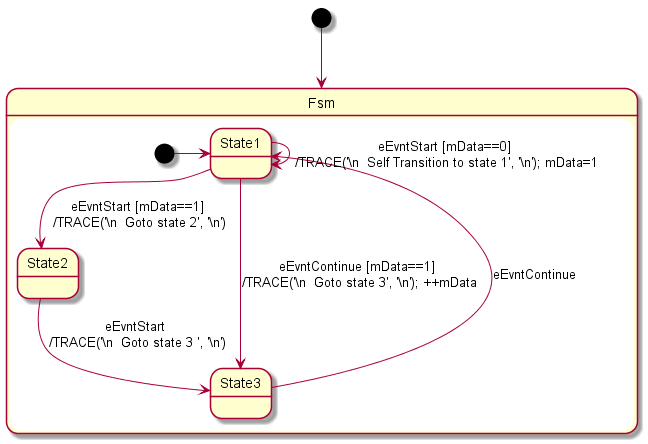
Figure 2: Generated UML Diagram
FSM_TT(tState, tEvent)
  FSM_TT_BEG( State1, State2, eEvntStart,    mData==1, TRACE("\n%S  ", "Goto state 2\n") )
  FSM_TT_CNT(         State1, eEvntStart,    mData==0, TRACE("\n%s  ", "Self Transition to state 1\n"); mData=1  )
  FSM_TT_CNT(         State3, eEvntContinue, mData==1, TRACE("\n%s  ", "Goto state 3\n"); ++mData  )
  FSM_TT_BEG( State2, State3, eEvntStart,    true, TRACE("\n%s  ", "Goto state 3 \n") )
  FSM_TT_BEG( State3, State1, eEvntContinue, true,  )
FSM_TT_END
FSM_TT_INIT( State1, mData=0 )

// <FSM_ST><attr>
int mData;
// </FSM_ST>
This table is stored in the file fsm.tt.
Note: The init tells the script that State 1 shall be set at startup and mData shall be set to 0.
Now call
perl fsm2plantuml_pl -tt fsm.tt -cpp MyFsm > fsm.cppThus the fsm.cpp template is created. Adapt the getEvent function for a test:
tEvent getEvent(void)
{
  // TODO: adapt to your needs for a test
  static int i = 0;
  static MyFsm::tEvent event[] = {
    MyFsm::eEvntStart,
    MyFsm::eEvntStart,
    MyFsm::eEvntStart,
    MyFsm::eEvntContinue,
    MyFsm::eEvntContinue,
    MyFsm::eEvntStart,
    MyFsm::eEventVoid
    };
Save the work, compile and execute in a windows command shell with cls && g++ -s fsm.cpp -o fsm.exe && fsm
Some notes on the class attribute mData.
The class attribute mData is added by the script via // <FSM_ST><attr> in
MyFsm
in the file fsm.cpp. Look at TODO in the code at the class declaration:
  tState mState;

  // TODO: enter other parts as necessary

  // <FSM_ST><attr>
  int mData;
  // </FSM_ST>
};
The variable becomes initialized via FSM_TT_INIT in the init method:
void MyFsm::init( tState StStart )
{
  TRACE_FUNC_ENTRY( StStart );
  mState = StStart;
  bDoTransition = FSM_ENTRY_INIT;
  mEventNew = eEventVoid;
  // TODO: initialization
  mData=0;
}